- Order number: Pololu-1366
- Manufacturer product ID: 1366
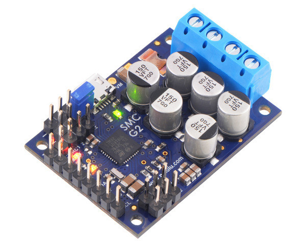
This powerful motor controller makes basic control of a brushed DC motor easy, with quick configuration over USB using our free software. It supports five control interfaces: USB, TTL serial, I²C, analog voltage (potentiometer), and hobby radio control (RC). This version offers a wide 6.5 V to 30 V operating range and can deliver continuous output currents up to 25 A without a heat sink. Male headers and terminal blocks are included but not soldered, allowing for custom installations.
 |
Overview
The Simple Motor Controllers are versatile, general-purpose single-channel motor controllers for brushed, DC motors. Wide operating voltage ranges and the ability to deliver up to several hundred watts in a small form factor make these controllers suitable for many motor control applications. With a variety of supported interfaces—USB for direct connection to a computer, TTL serial and I²C for use with embedded systems, RC hobby servo pulses for use as an RC-controlled electronic speed control (ESC), and analog voltages for use with a potentiometer or analog joystick—and a wide array of configurable settings, these motor controllers make it easy to add basic control of brushed DC motors to a variety of projects. A free configuration utility for Windows simplifies initial setup of the device and allows for in-system testing and monitoring of the controller via USB.
Details for item #1366
24 V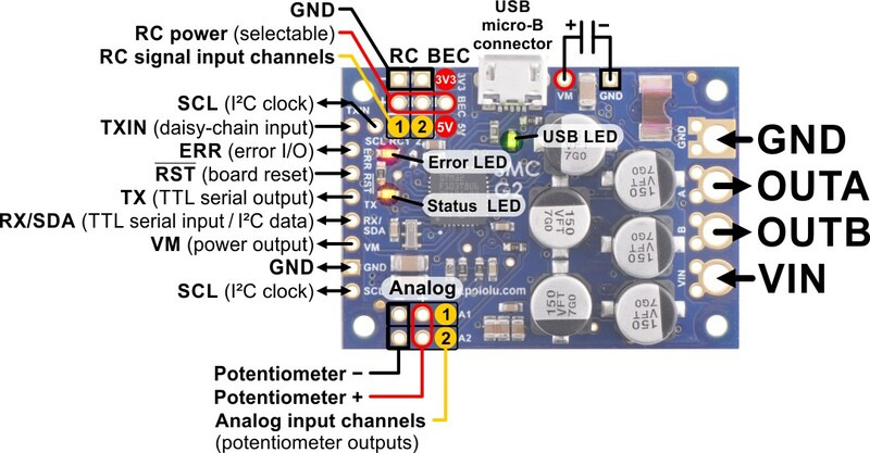 |
The SMC G2 18v25 operates from 6.5 V to 30 V and can deliver a continuous output current of 25 A without a heat sink. Note that 30 V is the absolute maximum for this controller; the maximum recommended operating voltage is 24 V, and the maximum recommended nominal battery voltage is 18 V. For applications using higher voltages (such as 24 V batteries), we recommend the higher-voltage SMC G2 24v12 or SMC G2 24v19.
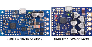
If you need to identify which version you have, you can just plug it into a computer through USB and the SMC software will tell you. For quick visual identification without a computer, you can distinguish this version from the identically sized SMC G2 24v19 by the number 150 on top of the tall silver electrolytic capacitors.
This version has header pins and terminal blocks included but not soldered, so soldering is required to use it.
|
|
Included hardware
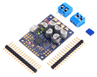 |
The SMC ships with a 0.1″ breakaway male header strip and two 2-pin 5mm terminal blocks. You can solder the terminal blocks to the four large through-holes to make your motor and motor power connections (see our short video on terminal block installation), or you can solder a couple of 2-pin pieces of the 0.1″ header strip into the smaller through-holes above and below these larger holes.
Pieces from the 0.1″ header strip can be soldered into the small holes on the logic connection side of the board to enable use with solderless breadboards, perfboards, or 0.1″ connectors. For the most compact installation, you can just solder wires directly to the holes.
Key features of the SMC G2 family
- Simple bidirectional control of one brushed DC motor
- Five communication or control options:
- USB interface for direct connection to a PC
- Logic-level (TTL) serial interface for use with a microcontroller
- I²C interface for use with a microcontroller
- Hobby radio control (RC) pulse width interface for direct connection to an RC receiver or RC servo controller
- 0 V to 3.3 V analog voltage interface for direct connection to potentiometers and analog joysticks
- Simple configuration and calibration over USB with a free configuration program for Windows
- Reverse-voltage protection
- Hardware current limiting with a configurable threshold
- Current sensing
Note: A USB A to Micro-B cable (not included) is required to connect this controller to a computer.
Additional features of the SMC G2 family
- Adjustable maximum acceleration and deceleration to limit electrical and mechanical stress on the system
- Adjustable starting speed and maximum speed
- Option to brake or coast when speed is zero
- Optional safety controls to avoid unexpectedly powering the motor
- Input calibration (learning) and adjustable scaling degree for analog and RC signals
- Under-voltage shutoff with hysteresis for use with batteries vulnerable to over-discharging (e.g. LiPo cells)
- Adjustable over-temperature threshold and response
- Adjustable PWM frequency from 1.13 kHz to 22.5 kHz (maximum frequency is ultrasonic, eliminating switching-induced audible motor shaft vibration)
- Error LED linked to a digital ERR output, and connecting the error outputs of multiple controllers together optionally causes all connected controllers to shut down when any one of them experiences an error
- Field-upgradeable firmware
Serial features:
Features of the serial, I²C, and USB interfaces:
- Optional CRC error detection to eliminate communication errors caused by noise or software faults
- Optional command timeout (shut off motors if communication ceases)
- Controllable from a computer via serial commands sent to the device’s USB virtual serial (COM) port, or via TTL serial through the device’s RX/TX pins
- TTL serial uses 0 V and 3.3 V on TX, accepts 0 V to 5 V on RX
- Supports automatic baud rate detection from 1200 bps to 500 kbps, or can be configured to run at a fixed baud rate
- Supports standard compact and Pololu protocols as well as the Scott Edwards Mini SSC protocol and an ASCII protocol for simple serial control from a terminal program
- Optional serial response delay for communicating with half-duplex controllers such as the Basic Stamp
- Controllers can be easily chained together and to other Pololu serial motor and servo controllers to control hundreds of motors using a single serial line
1) I²C features:
- Compatible with I²C bus voltage levels from 1.8 V to 5 V
2) USB features:
- Full-speed USB interface (12 Mbps)
- Example code in C#, Visual Basic .NET, and Visual C++ is available in the Pololu USB Software Development Kit
3) RC features:
- 1/4 µs pulse measurement resolution
- Works with RC pulse frequencies from 10 to 333 Hz
- Configurable parameters for determining what constitutes an acceptable RC signal
- Two RC channels allow for single-stick (mixed) motor control, making it easy to use two simple motor controllers in tandem on an RC-controlled differential-drive robot
- RC channels can be used in any mode as limit or kill switches (e.g. use an RC receiver to trigger a kill switch on your autonomous robot)
- Battery elimination circuit (BEC) jumper can power the RC receiver with 5 V or 3.3 V
4) Analog features:
- 0.8 mV (12-bit) measurement resolution
- Works with 0 to 3.3 V inputs
- Optional potentiometer/joystick disconnect detection
- Two analog channels allow for single-stick (mixed) motor control, making it easy to use two simple motor controllers in tandem on a joystick-controlled differential-drive robot
- Analog channels can be used in any mode as limit or kill switches
This video demonstrates the versatility of the Simple Motor Controller by showing how it can be controlled directly from the analog output of a Sharp analog distance sensor—there is no intermediate control board and no programming involved. The unit in the video is one of our original SMCs, but the newer SMC G2s have the same capabilities.
Comparison to the original Simple Motor Controllers
The SMC G2 family features a number of improvements compared to our original Simple Motor Controllers with green PCBs:
- Reverse voltage protection
- Configurable hardware current limiting – the motor drivers on the SMC G2 use current chopping to actively limit the motor current when it exceeds a software-configurable threshold
- I²C interface provides an additional control option
- USB Micro-B connector (instead of Mini-B as on the original SMCs)
- The SMC G2 18v25 and 24v19 use a four-layer board with double-sided assembly, which lets them be much smaller than their original counterparts (the SMC 18v25 and 24v23)
The SMC G2 controllers have the same pin arrangements as the original SMCs, so they should be usable as drop-in replacements in typical applications, though note that the minimum operating voltage is a little higher for the G2 versions (6.5 V vs 5.5 V for the originals). The SMC G2 serial protocol is compatible with (and generally a superset of) the original SMC serial protocol, so in most cases, serial interface software running on a microcontroller or computer will not need to be modified to work with a SMC G2.
Dimensions
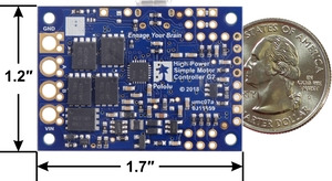
| Size: | 1.7″ × 1.2″ × 0.42″ |
|---|
General specifications
| Motor channels: | 1 |
|---|---|
| Control interface: | USB; non-inverted TTL serial; I²C; RC servo pulses; analog voltage2 |
| Minimum operating voltage: | 6.5 V |
| Maximum operating voltage: | 30 V |
| Continuous output current per channel: | 25 A |
| Maximum PWM frequency: | 22.5 kHz |
| Maximum logic voltage: | 3.3 V |
| Reverse voltage protection?: | Y |
| Version: | G2 18v25 (30 V max, 25 A max continuous) |
| Connectors soldered?: | N |
Notes:
1. Autodetects baud rates between 1200 and 500,000 bps, or can be set to any fixed baud rate in this range.
2. Absolute maximum; higher voltages can permanently destroy the motor driver. Recommended maximum is approximately 24 V, which leaves a safety margin for ripple voltage on the supply line.Not recommended for use with 24V batteries.
3. Typical results at room temperature running at 90% duty cycle.
4. All digital inputs are 5V tolerant.


